Tuesday, December 23, 2014

Setting up an ARM Cortex®-A9 based SBC

The RIoTboard is an ARM Cortex-A9 based single board computer (SBC). The RIoTboard has a Freescale i.MX6 Solo application processor and an integrated Freescale Kinetis MCU for additional debugging and development. The i.MX6 Solo supports the single ARM Cortex-A9 MPCore Platform. The i.MX6 Solo contains ARM TrustZone technology and the i.MX 6 SoC on the RIoTboard has a 96 KB Boot Rom with support for high assurance boot. Other features of the board include 1 GB of DDR3 memory, 4 GB eMMC, JTAG, Serial, mini USB for OpenSDA, mini USB for USB OTG, LVDS, parallel RGB expansion, 4 USB-A ports, HDMI, audio, reset button, microSD card slot, SD card slot, and boot onboard boot switches. The board is very reasonably priced. Last but not least, the Freescale i.MX 6 ARM Cortex-A9 application processor has ARM TrustZone technology.

The i.MX6 Solo processor on the RIoTboard is labeled MCIMX6S8DVM10AB. According to the i.MX6 Solo data sheet, the processor supports a number of security related features. The list includes ARM TrustZone technology with TZ architecture support, a secure JTAG controller for locking down and protecting the JTAG port, a cryptographic acceleration and assurance module with secure RAM and a true PRNG, a central security unit (CSU) including secure non-volatile storage, high assurance boot, and the separation of memory and interrupts between secure world and normal world. There are more security related features but this is a general list.

Setting up a RIoTboard

Embedded devices used for development purposes often have network controllers on them.  From mobile phones to radios, routers, watches, and wearables, these devices are sending and receiving IP datagrams to external Internet hosts via one or many of their network interfaces; WiFi, 3G, 4G, and Bluetooth.  Most of the processors being sold today can run rich operating systems with full software support for multiple network interface controllers.  In addition, many of the processors being sold today contain support for both virtualization and trusted execution. 

A network router that is isolated from the Internet and any local computers can be connected to the embedded device via the device's primary network interface. If there are multiple network interfaces on the embedded device, then multiple routers can be connected to the embedded device - one for each interface type. 3G and 4G routers, while not widely available, can be connected to the 3G or 4G modem on the embedded device.

IP traffic can be sent and received from both secure world and normal world via multiple network interfaces.  Raw packet analysis tools on the router can be used to inspect incoming and outgoing traffic from the embedded device.  After the router is connected to the embedded device, data that is transmitted over the embedded device's network interface can be recorded to a format such as PCAP and saved for later analysis.  A firewall can also be deployed on the router and all outgoing traffic originating from the embedded device can be blocked.  Inexpensive routers with ARM based processors and ARM TrustZone technology can be purchased from most retail stores.

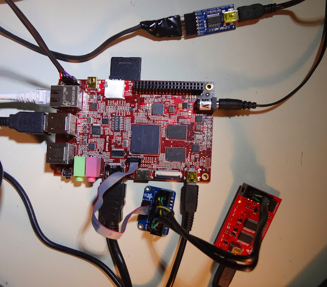
Short of having access to JTAG hardware debuggers, a Bus Pirate can be used in conjunction with OpenOCD for debugging the i.MX 6 processor on the RiOTboard. A bus pirate can also be used in transparent UART bridge mode for connecting the host to the target (the RiOTboard).

This type of setup can be very useful for debugging embedded devices, analyzing embedded devices, developing software for embedded devices, and testing embedded devices prior to production.


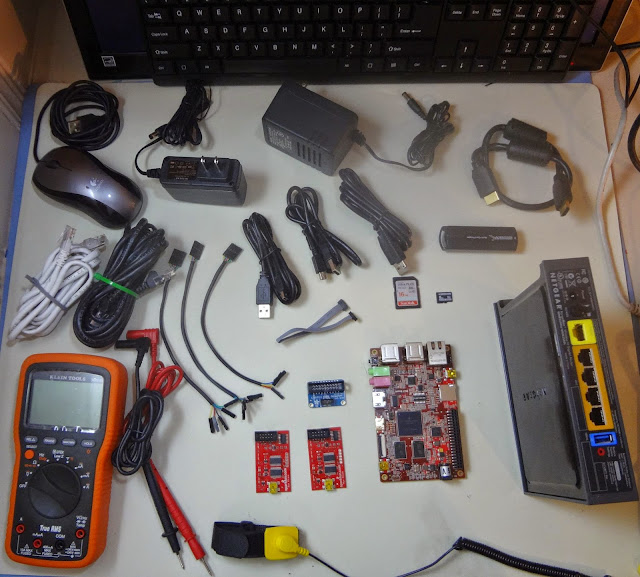
The Netgear WNR3500U (right) can run multiple operating systems.


  • Digital multimeter for testing continuity of JTAG, SWD, and Serial cables
  • Proper ground and wrist strap
  • 2x ethernet cable
  • WNR3500U router
  • microSD card 8 GB Class I
  • SD card 8 GB Class I
  • RiOTboard
  • 5 VDC power supply for RiOTboard
  • 2x Bus Pirate
  • Cortex SWD 10 to 20 pin adapter
  • 2x 5-pin female to female breakout cable
  • FTDI mini USB to 5-pin female breakout board
  • 4-pin female to female breakout cable
  • HDMI cable
  • USB mouse
  • USB keyboard
  • Display
  • Host computer with Linux (Fedora 21)
  • 4x mini USB to USB-A cables
  • 10-pin female to female SWD / JTAG cable
  • Card reader

Using the Bus Pirate as a transparent UART bridge

Bus Pirate Pin 01 GND  <---> RiOTboard J18 Pin 3 GND
Bus Pirate Pin 08 MOSI <---> RiOTboard J18 Pin 1 UART2 TX
Bus Pirate Pin 10 MISO <---> RiOTboard J18 Pin 2 UART2 RX

Flashing the PIC on the Bus Pirate is straightforward (see documentation) and should be performed so that the Bus Pirate is running the latest firmware.

RiOTboard connected via JTAG and UART to Host


Monday, December 15, 2014

ARM, NFC Technology, and the Single Wire Protocol

At the heart of an ARM Powered smartphone with NFC technology is the contactless front end or CLF. The CLF is responsible for managing radio-frequency communication at 13.56 MHz.

A mobile phone with NFC technology contains only one CLF. The CLF is connected to the ARM processor or application processor via UART, I²C, and SPI. These protocols are relatively basic and facilitate straightforward communication between the application processor and CLF via a typical Linux or UNIX-based kernel. Updating the firmware on the CLF is a typical operation performed over the UART serial line.

While a mobile phone with NFC technology contains only one CLF, the phone may contain multiple secure elements. A secure element may reside on the UICC card, on the microSD card, or embedded with the CLF on the PCB. Applets residing on each of the secure elements can serve both similar and different purposes. Both the secure element and the CLF are small, self-contained computers with I/O communications interfaces. In the case where multiple secure elements reside on the phone, each of the secure elements is a small, self-contained computer with I/O communication interfaces. A secure element differs from a normal computer in that it is embedded and has limited resources available for performing computations.

A typical secure element also contains dedicated hardware co-processors for performing common cryptographic operations. Implementing standard cryptographic algorithms at the software level on the secure element is not always practical due to the resource constraints of the secure element components. At a high level, the applet(s) 's responsibility resides on the secure element is to handle the secure storage and transmission of private data. For these types of use cases, encryption and decryption are common operations. Consequently, they are refactored into hardware blocks on most secure elements.

UICC-based SEs, eSEs, and microSD-based SEs all use cryptography to store private data. UICC-based SEs, eSEs, and microSD-based SEs are typically manufactured by different companies. Consequently, multiple types of operating systems run on secure elements.

When the secure element is packaged with the CLF on the PCB, it is called the embedded secure element (eSE). The eSE is connected to the CLF via S2C (NFC-WI) for such a configuration.

By design, the inclusion of the embedded SE into the IC package with the CLF means that the provisioning of trusted applets, such as those used for e-ticketing, can occur via a communications channel external to that of the carrier-controlled, baseband processor. Updates and network communication with a UICC-based SE occur via the baseband processor. On the contrary, an eSE is not typically provisioned by the MNO when the phone is purchased. If the user has access to the proper access keys, communication with an embedded SE (eSE) can occur via the CLF through the application processor. The eSE is connected to the CLF in the IC package via the S2C bus. The S2C or NFC-WI interface was initially proposed by Philips and subsequently standardized by ECMA. The S2C interface consists of two lines, SigIn and SigOut, implemented as two physical wires between the CLF and embedded secure element. This S2C protocol allows for full-duplex communication over two physical wires between the CLF and eSE. A common eSE is called the NXP SmartMX.

In contrast, the UICC on a mobile phone has traditionally been used by the mobile network operators (MNOs) for carrier-specific purposes such as network subscriber information. Mobile phones with NFC technology and a UICC also utilize the secure element on the UICC for e-ticketing applications. The MNOs have primarily been involved in utilizing the secure element on the UICC for storing private data. The UICC-based SE manufacturer is most likely some entity other than NXP. The applets that reside on the UICC-based SE are inherently the domain of the mobile network operators. Applets running on the UICC are used for multiple purposes, including carrier network and subscriber information and NFC e-ticketing applications. Applications responsible for storing private data are provisioned by trusted external entities associated with the MNOs. Currently, the UICC-based SE is provisioned by a trusted MNO entity prior to purchase. Carrier network activities such as call initiation and SMS receipt can be communicated to/from applets running on the UICC via the radio interface software layer running on the application processor's operating system as the application processor is connected to the baseband processor. This exchange occurs in the form of APDUs. APDUs are exchanged between a contactless point of sale terminal and an applet running on the UICC-based SE or eSE during an NFC e-ticketing activity.

Since the inception of NFC hardware on ARM Powered smartphones, NFC e-ticketing applets have been added to the secure element on the UICC. The UICC is physically connected to the phone's baseband processor. The UICC is connected to the CLF via the single wire protocol (SWP) for a phone with NFC technology. A single, physical wire is connected between the CLF and one of the contact pins on the UICC. SWP defines the connection between the UICC and CLF. SWP is intended for use when the UICC-based SE houses trusted applets responsible for e-ticketing applications and private data storage. SWP allows full-duplex communication over a single physical wire between the CLF and UICC. ETSI TS 102 613 defines the physical and data layers of SWP. SWP was established by Gemplus (now Gemalto).

In the United States, MNOs utilize the secure element on the UICC card for hosting e-ticketing applications and storing private data. Android phones with NFC technology may an application that uses the RF controller on the phone. If this is the case, the phone most likely contains a UICC-based secure element connected to the internal CLF via the SWP.

The mobile phone may contain an NXP PN544 pin-to-pin compatible PN65N, in which case, the SWP line is wired to the UICC SWP contact pin via a single physical wire. Alternatively, the phone may contain a PN544 CLF, in which case the same SWP line is wired to the UICC SWP contact pin via a single physical wire. When an embedded secure element is connected to the CLF via S2C (NFC-WI) and the CLF is also connected to the UICC-based SE over the single wire protocol (SWP), then applications (applets) can be selected by id from either secure element.

The provisioning of applets to either the eSE, microSD SE, or UICC-based SE occurs via different channels. The MNOs have primarily been responsible for the provisioning of applets to the UICC-based SE via trusted third parties. In contrast, device manufacturers can provision parts of the embedded secure element before it leaves the factory. The physical connection to the secure element is one of its key differentiating factors. Embedded secure elements are connected to the CLF via S2C. In contrast, UICCs use the SWP pin to connect with the CLF. When an e-ticketing transaction occurs via NFC, it does so over the contactless communication interface. The remote e-ticketing terminal sends information back and forth between the applet running on the secure element. This communication occurs via the CLF to the SE, either over the single wire connection to a UICC-based SE or over the two-wire (S2C) connection to the eSE; depending on which SE is running the issuers e-ticketing applet. The MNO may provision the UICC-based SE with special applications. The microSD card is also connected to the CLF; however, this is not mentioned since microSD-based secure elements are not as prevalent yet in the United States.

It has been the intent of the OEMs (not all), silicon manufacturers (not all), and those in favor of open ecosystems to utilize the onboard embedded secure element (eSE) for hosting the applications that are responsible for e-ticketing applications.

There are multiple parties involved in this ecosystem; they include and are not limited to trusted third parties responsible for provisioning applets to the secure element via the carrier network, credit card issuers, silicon manufacturers, original equipment manufacturers (OEMs), banks, mobile network operators (MNOs), software vendors such as Google, credit card manufacturers, credit card issuers global standards bodies such as ISO and EMVCo, trusted service managers, service providers, certificate authorities, industry associations such as Global Platform, and numerous regulating entities. The ecosystem is complex, and there are currently several successful efforts underway to standardize NFC technology and how it is used in the United States.

As a critical point to consider and in contrast to the solutions that have been implemented for the safe execution and storage of NFC related e-ticketing applications and private data, ARM TrustZone technology in the processor core can be utilized in a similar light to that of the technologies on the eSE, UICC-based SE, and microSD SE. ARM TrustZone technology provides an ideal platform for secure keypad entry and user authentication.
Friday, December 12, 2014

ARM Powered smartphones with NFC technology

There are many Near Field Communication (NFC)-enabled phones (devices) available on the consumer market. LG, Huawei, Motorola, Samsung, HTC, Nokia, ZTE, Sony, RIM, Amazon, and Apple are among the companies that manufacture and sell mobile phones with NFC technology.

There are many common denominators at the hardware and software levels among all the phones that have NFC technology. First, all mobile phones contain a main (application) processor, and if the phone is manufactured by one of the companies listed above, the application processor is an ARM microprocessor. There may be one or two exceptions, but if 150 current phones were sampled across all of these manufacturers, one would find that 99% of the phones contain ARM technology. Operating systems that run on the ARM Powered processors contained within phones from these manufacturers are similar in that they support preemptive multitasking. Most of these devices run the Linux operating system or a UNIX-based operating system.

An ARM Powered smartphone with NFC technology contains other microprocessors on its printed circuit board (PCB). These other microprocessors consist of the radio frequency (RF) controller or contactless front end (CLF) and an optional embedded secure element (eSE). The CLF is responsible for managing contactless communication at 13.56MHz. The eSE and SE (external UICC-based or microSD card-based) are responsible for secure application execution and the secure storage of sensitive payment or identification information. A trusted OS runs on the eSE and/or SE. A mobile phone may contain both an eSE and a UICC-based or microSD-based SE. For such a configuration where multiple secure elements exist on the phone, different trusted operating systems may run on the phone's secure elements, and different trusted applications (client applications) may run on the trusted operating systems. One trusted application may be responsible for secure VISA payments, and another trusted application may be responsible for electronic identification (eIdentification).

The RF controller and the embedded secure element (eSE) are soldered directly to the PCB, typically within the same IC package. The RF controller may exist on the circuit board without the eSE. The eSE is an optional hardware component on a mobile phone that contains NFC technology. The RF controller and eSE are soldered to the PCB by the phone manufacturer. Alternatively, the secure element used for NFC may be external. An external secure element is one that is located on the mobile phone's UICC or microSD card. When a mobile phone is purchased from a local cell phone store, a UICC card is usually inserted into the phone by the person at the store. If purchased from one of the leading operators in the United States, the UICC card contains a secure element. It is important to note that the existence of an embedded secure element and a UICC-based or microSD-based secure element on the same mobile phone is not mutually exclusive. The secure elements may serve different purposes.

As mentioned above, ARM Powered smartphones with NFC technology may contain a single type of secure element. Such a phone may only contain a CLF or RF controller. Mobile phones with a CLF and no secure element may emulate the software running on the secure element via the operating system and application software running on the application processor. This is called host card emulation (HCE).

There are numerous configurations of NFC technology on mobile phones. Each of the described components exposes one or more hardware interfaces for communication and interconnection with neighboring components on the printed circuit board. Hardware bus protocols and software communication protocols run on top of the wires that connect the individual components on the printed circuit board. These include standard bus protocols such as I²C, S2C (NFC-WI), SWP, and SPI (more on this later). It is important to note that a typical ARM-powered smartphone with NFC technology has a CLF that is connected to the application processor via both I²C and UART. This is good because I²C device drivers are not complicated, and reading/writing to a tty on an ARM-powered smartphone is straightforward. Lastly, the CLF typically contains an optimized 80C51 processor. The CLF may be packaged with a secure element, and the secure element may contain an optimized 8051 core or newer RISC-based core. The secure element will also contain dedicated crypto co-processors for performing asymmetric or symmetric cryptographic operations (i.e., FameX). Custom firmware runs on the CLF, and it can usually be updated via the host operating system over UART. 80C51 firmware for the CLF is usually C code (more on this later). A trusted OS (e.g., JCOP) and trusted applications (applets) run on the secure element. Lastly, if the CLF and secure element are contained within a single IC soldered onto the PCB, they are usually connected via S2C (NFC-WI) internally. As a side note, ARM designs and manufactures ARM Keil development boards. Arm Keil and Ashling are two of the most prevalent companies that sell compilers and development toolkits for embedded microprocessors such as the 80C51. Ashling sells an excellent series of in-circuit emulators (ICE) for debugging SmartMX and SmartMX2 microcontrollers.

Monday, December 8, 2014

The ARM Cortex-A9 Processor - Real World Uses

The ARM Cortex-A processor is commonly used in compute-intensive applications. These processors are capable of running full or rich operating systems such as Linux or UNIX. In the previous blog post, I mentioned the ARM Cortex-A9 based MPCore. The ARM Cortex-A9 processor is highly configurable and is implemented by Freescale Semiconductor in their i.MX 6 processor. The i.MX 6 processor is available in a variety of configurations, including lite, single, dual, dual-lite, and quad-core, and is used in critical applications across multiple industries, including aerospace, medical, and industrial. i.MX processors can be found in devices such as Medical-CT scanners, ultrasound machines, automotive telematics systems, e-readers, and more. Due to their power efficiency, i.MX 6 processors are also suitable for wearables such as glasses and watches.

One example of a device powered by the i.MX 6 is the OrCam, a clip-on wearable designed for users with vision impairments. The OrCam clips onto a pair of eyeglasses and scans the user's field of vision, detecting objects and providing aural feedback via a bone conduction earpiece.

Another device that uses the i.MX 6 processor is the Kindle Fire HD 6 tablet. It's worth keeping an eye out for other wearables, watches, and glasses that use the i.MX 6 processor.

In terms of development, the i.MX 6 is an ideal choice. Although the manuals and data sheets for the processor are quite lengthy, the one-time programmable memory locations or eFuses on the i.MX 6 are highly configurable. eFuses are standard in higher-end microprocessors and can be read or blown (one-time write to an on-chip memory location) using u-boot or the Freescale manufacturing tool. They can also be pulled via the Linux sysfs interface. Typically, there are over 100 eFuses on higher-end microprocessors, and they store important values such as the MAC address, boot configuration parameters, high-assurance boot (HAB) configuration parameters, and master key. U-boot conveniently supports reading and writing (blowing) the eFuses on many different microprocessors. U-boot is open source and supports one-time programmable memory (eFuses or OTP) on ARM-based processors. The U-Boot bootloader also supports a large number of chipsets, including ARM, AVR32, Blackfin, MicroBlaze, MIPS, PPC, and x86.

Sunday, December 7, 2014

ARM TrustZone technology - from Monitor Mode to Dedicated Security Co-Processing and the Secure Element(s)

"A design that places sensitive resources in the Secure world and implements robust software running on the secure processor cores can protect assets against many possible attacks, including those that are normally difficult to secure, such as passwords entered using a keyboard or touch-screen. By separating security-sensitive peripherals through hardware, a designer can limit the number of sub-systems that need to go through security evaluation and therefore save costs when submitting a device for security certification." - ARM.com

NOTE: There are variations in how software is implemented in the secure world - from a simple synchronous library of code to a full-blown operating system.

The execution of the normal OS and secure OS is interleaved over time via a context-switching mechanism called monitor mode. Monitor mode is responsible for time-slicing the execution of the normal OS and secure OS via context switching the state of each world on the physical processor. Monitor mode is explicitly triggered via a dedicated instruction or special type of exception. The explicit methods by which monitor mode is triggered contrast the typical scheduling algorithms that trigger context switching in modern-day preemptive operating systems.

There are varying levels of complexity regarding how the physical hardware in which the secure world runs is designed. These range from both worlds running on the same physical processor core to the secure world running on a completely separate processor core.

Another type of physical hardware design entails an additional microprocessor that is separate from the main processor. The secure world software stack (secure OS and secure applications) runs on a dedicated co-processor. This design is not exclusive to a secure OS running on the main ARM processor. The normal OS still runs on the main ARM processor, and a secure OS can still run on the main ARM processor if the main ARM processor has ARM TrustZone technology. A different secure OS and secure application software can run on the dedicated co-processor.

Client applications running on a secure OS can communicate with the main ARM processor via a set of APIs and commands. There are certain benefits to the secure OS always running on a dedicated security processor core or co-processor.

The operating system that runs on the co-processor can be optimized for just the co-processor. There are many types of dedicated co-processors. The ARM SecurCore microprocessor is one type of dedicated co-processor. ARM SecurCore microprocessors are used in systems that require dedicated processors for security-sensitive applications such as SIM cards, e-Government, Banking, and Identification. Designs that incorporate ARM SecurCore microprocessors can realize multiple key benefits including build performance improvements, energy efficiency, and physical security. Designing and building an operating system for a single chip means that the operating system can be built to use all of the features and only those features that the chip provides.

In summary, here are the key points:
  • Operating system software runs on the main ARM processor or application processor. Software applications run on the application processor. ARM processors in ARM-based mobile phones may or may not have TrustZone processor security technology. If the ARM processor has TrustZone processor security technology, then it may or may not be used.
  • There are additional processors on mobile phones that act as dedicated security co-processors. These include the secure element on the UICC or SIM card (UICC-based SE) and the secure element that has been soldered on the printed circuit board. The secure element that has been soldered to the printed circuit board is called the embedded SE. The iPhone 6, iPhone 6 Plus, Samsung S5, Galaxy Nexus, Nexus S, Nexus 7, Sony Xperia series, and a host of others contain a secure element soldered onto the printed circuit board. If the phone has a secure element that has been soldered onto the printed circuit board, then it is most likely contained within the packaging of a larger SoC that also contains the Near Field Communication (NFC) Radio-Frequency (RF) controller. Last but not least, it is entirely possible that the phone contains a secure element on the microSD card.
  • The embedded SE and UICC-based SE run a trusted OS. Trusted applications run on top of the trusted OS. In contrast to the trusted OS that runs within the secure world on a main ARM processor with ARM TrustZone processor security technology, the trusted OS that runs on the embedded SE and UICC-based SE does not share full hardware peripheral or direct normal world software access on the main application processor.
  • The UICC-based SE and embedded SE are protected by cryptographic keys. Client software applications running on the trusted OS in a processor with ARM TrustZone architecture security extensions are also protected by cryptographic keys.
  • There are multiple standards bodies that have established APIs, architecture documents, design documents, and so forth for the trusted operating system and trusted applications that run on the UICC-based SE and embedded SE. These entities are also responsible for the hardware interface on the physical secure element.

ARM TrustZone technology - a Few Good Boards

ARM provides the Juno ARM Development Platform, a reference platform for software and hardware developers building systems based on ARM Cortex-A processors. This platform contains a board that houses an ARM Cortex-A57 processor and the ARM Cortex-A53 MPCore processor. Both processors are 64-bit and implement the ARMv8-A instruction set architecture (ISA). Developers can build a board support package for this board using OpenEmbedded/Yocto.

The Apple A7 and Apple A8 chips found in the iPhone 5c, iPhone 5s, iPhone 6, and iPhone 6 Plus are based on the ARM Cortex-A53 and the ARM Cortex-A57. Additionally, the Samsung Exynos 5433 Octa SoC contains the ARM Cortex-A57 and the ARM Cortex-A53 MPCore, while the Samsung Galaxy Note 4 has an 8-core Exynos 5433 processor.

The Nvidia TK1 development board, which has a quad-core ARM Cortex-A15 processor, is currently available for purchase. However, the latest board from Nvidia, known as "Denver", which is rumored to contain the ARM Cortex-A57 and the ARM Cortex-A53 MPCore, is not yet available for purchase.

The Freescale I.MX 6 processor has been widely adopted across various industries for a range of embedded products. Freescale offers the SABRE board for intelligent devices, a development board that features the I.MX 6 Quad-Core ARM Cortex-A9 processor. Boundary Devices also sells their variation of this board with the same ARM Cortex-A9 MPCore. Developers can build a board support package for both the Freescale SABRE board and the Boundary Devices board using OpenEmbedded/Yocto.

When working with ARM development boards, it is important to take into account a few critical features. Specifically, e-fuses should not be blown out of the box and should be left open. The fuses can be blown to fit a specific configuration.

Here is a quick overview of the processors and boards.

Processor
Manuf
ISA
Dev Board
TrustZone
ARM Cortex-A57 and ARM Cortex-A53 MPCoreARMARMv8-AJuno Ref PlatformYes
ARM Cortex-A15NvidiaARMv7TK1Yes
ARM Cortex-A15SamsungARMv7Arndale Exynos 5420Yes
ARM Cortex-A9 MPCoreFreescaleARMv7Freescale SABREYes
ARM Cortex-A9 MPCoreFreescaleARMv7Boundary DevicesYes
ARM Cortex-A9 MPCore + Zync 7000 FPGAXilinxARMv7Zed BoardYes
ARM Cortex-A9 MPCore + Zync 7000 FPGAXilinxARMv7Digilent                 
Yes

Friday, November 21, 2014

C++ - Generative Programming

C++ IOStreams are a powerful mechanism for transforming input into output. Most programmers are at least familiar with C++ IOStreams in the context of reading and writing bytes to a terminal or file.

When a file or terminal is opened for reading or writing by a process, the operating system returns a numerical identifier to the process. This numerical identifier is known as a file descriptor. In turn, the file or terminal can be written to by the process via this file descriptor. The read and write system calls, which are implemented as wrappers in libc, are passed this numerical file descriptor.

Many layers of abstraction reside on top of the read and write system calls. These layers of abstraction are implemented in both C and C++. Examples of C-based layers of abstraction are fprintf and printf. Internally, these functions call the write system call. An example of a C++-based layer of abstraction is the IOStreams hierarchy. Out of the box, most C++ compiler toolchains provide an implementation of IOStreams. IOStreams are an abstraction on top of the read and write system calls. When data is written to a terminal via an IOStream, the IOStream implementation calls the write system call. Lastly, these layers of abstraction handle things such as buffering and file synchronization.

In UNIX, everything is a file. Consequently, network devices, virtual terminals, files, block devices, etc., can all be written to via a numerical file descriptor - this in turn is why UNIX is referred to as having a uniform descriptor space. With this being said, the basic IOStreams and printf abstractions I mentioned above are not designed to be used with network sockets, pipes, and the like. The lower-layer read and write system calls can be used, but there are a number of functions that must be called before writing raw bytes to an open file descriptor that points to a network socket.

The additional functionality that is needed for communicating with network sockets, shared memory, and the like can be implemented in classes that are derived from the C++ iostream class. It is for this reason that the IOStreams classes are extended via inheritance.

Over the years, several popular C++ libraries have implemented classes that are derived from the base classes in the iostreams hierarchy. The C++ Boost library is a popular example. However, this has not always been the case. Going back to 1999, the Boost library did not exist, and there were one or two examples on the entire Internet as to how to properly extend the C++ IOStreams classes.

In 1999, the source code for the GNU compiler toolchain that is available on gcc.gnu.org was obtained, and a class hierarchy was derived to support sockets, pipes, and shared memory. The methods in the classes derived from the base classes in the iostreams library were designed to be reentrant and easy to use. Generative programming techniques and template metaprogramming were used to create objects that could be instantiated using familiar C++ iostreams syntax and semantics. The library created was called mls, and it was licensed under version 2 of the GPL.

Since 1999, Boost has come a long way. It provides support for cryptographic IOStreams, sockets, and all kinds of other fancy stuff. It uses generative programming techniques.The GCC compiler toolchain can be obtained from gcc.gnu.org. Ctags can then be used to dig into the internals of the IOStreams hierarchy. The following book is recommended: Generative Programming - Methods, Tools, and Applications.

The gcc compiler toolchain can be obained from gcc.gnu.org. Ctags can then be used to dig into the internals of the iostreams hierarchy.. The following book is recommended.
Generative Programming - Methods, Tools, and Applications

namespace mls
{
template<class BufType, int direction, class BaseType=mlbuf> class mlstreamimpl;
template<class Parent, class BaseType=mlbuf> class mloutputimpl;
template<class Parent, class BaseType=mlbuf> class mlinputimpl;
template<class BufType, int direction, class BaseType=BufType>
struct StreamConfig;
template<class BufType, int direction, class BaseType>
struct StreamConfig
{
typedef typename SWITCH<(direction),
CASE<0,mlinputimpl<mlstreamimpl<BufType, direction, BaseType>, BufType>,
CASE<1,mloutputimpl<mlstreamimpl<BufType, direction, BaseType>, BufType>,
CASE<10,mlinputimpl<mloutputimpl<mlstreamimpl<BufType, direction, BaseType>,
BufType>, BufType >,
CASE<DEFAULT,mlinputimpl<mlstreamimpl<BufType, 10, BaseType>,
BufType > > > > > >::RET Base;
};
}