Sunday, September 2, 2018

96Boards - JTAG and serial UART configuration for ARM powered, single-board computers

The 96boards CE specification calls for an optional JTAG connection. The specification also indicates that the optional JTAG connection shall use a 10 pin through hole, .05" (1.27mm) pitch JTAG connector. The part is readily available on most electronics sites. Breaking out the pins with long wires and shrink wrapping them is ideal for making sure that each connection is labeled and separate when connecting to a JTAG debugger. While a JTAG connection is not required for flashing or loading the bootloaders onto the board, the JTAG connection is useful for advanced chip-level debugging. The serial UART connection is sufficient for loading release or debug versions of bl0, bl1, bl2, bl31, bl32, the kernel, and userspace.  Last but not least, ARM-powered boards, with 12V power input, often require external fans to keep the board cool. As seen in the below photos, two 5V fans were powered from an external power supply. Any work on microcontroller boards should be performed on a grounded surface.  Proper grounding procedures should always be followed as most microcontroller boards contain ESD sensitive components.

In the below photos, a 96Boards SBC is mounted on an IP65, ABS plastic junction box for durability. The pins are extended and mounted with screws underneath the junction box. The electrical conduit holes on the side of the junction box are ideal for holding small, project fans. The remaining electrical conduit holes provide a clean place to place the remaining wires from the board - micro USB, USB-C, and 12V power.


Thursday, June 7, 2018

HiKey 960 Linux Bridged Firewall

The Kirin 960 SoC and on-board USB 3.0 make the HiKey 960 SBC an ideal platform for running a Linux Bridged firewall. The number of single-board computers with an SoC as powerful as the HiSilicon Kirin 960 are limited.

When compared with the Raspberry Pi series of single board computers (SBC), the HiKey 960 SBC is significantly more powerful. The Kirin 960 also stands above the ARM powered SoCs which reside in most commercial routers.

USB 3.0 makes the HiKey 960 board an attractive option for bridging or routing, filtering network traffic, or connecting to an external gateway via IPSec. Both network traffic filtering and IPSec tunneling can be computationally expensive operations. However; the multicore Kirin 960 is well suited for these types of tasks.

In order to be able to run an IPSec client tunnel and a Linux Bridged firewall connected over 1G ethernet links, certain kernel configuration modifications are needed. Furthermore, the Android Linux kernel for the HiKey 960 board does not boot on a standard Linux root filesystem because it is designed to boot an Android customized rootfs.

The latest googlesource Linux kernel (hikey-linaro-4.9) for Android (designed to boot Android on the HiKey 960 board) has been customized to remove the Android specific components so that the kernel boots on a standard Linux root filesystem, with the proper drivers enabled for network connectivity via attached 1000Mb/s USB 3.0 to ethernet adapters. The standard UART interface on the board should be used for serial connectivity and shell access. WiFi and Bluetooth have been removed from the kernel configuration. The kernel should be booted off of a microSDHC UHS-I card. The 96boards instructions should be followed for configuring the HiKey 960 board, setting the jumpers on the board, building and flashing the l-loader, firmware package, partition tables, UEFI loader, ARM Trusted Firmware, and optional Op-TEE. Links for the normal Linux kernel configuration, multi-interface bridge configuration, and single interface IPSec configuration are below. Additional kernel config modifications may be needed for certain types of applications.

kernel build instructions


mkdir /usr/local/toolchains
cd /usr/local/toolchains/
wget https://releases.linaro.org/components/toolchain/binaries/latest/aarch64-linux-gnu/gcc-linaro-7.2.1-2017.11-x86_64_aarch64-linux-gnu.tar.xz
tar -xJf gcc-linaro-7.2.1-2017.11-x86_64_aarch64-linux-gnu.tar.xz
export ARCH=arm64
export CROSS_COMPILE=/usr/local/toolchains/gcc-linaro-7.2.1-2017.11-x86_64_aarch64-linux-gnu/bin/aarch64-linux-gnu-
export PATH=/usr/local/toolchains/gcc-linaro-7.2.1-2017.11-x86_64_aarch64-linux-gnu/gcc-aarch64-linux-gnu/bin:$PATH
cd /usr/local/src
git clone https://android.googlesource.com/kernel/hikey-linaro
cd hikey-linaro
git checkout -b android-hikey-linaro-4.9 
make hikey960_defconfig
make -j8

multi-interface bridge configuration 

Bridged configuration, no ip addresses on dual nic interfaces. (crossover cable is useful for testing). Bridge interface obtains dhcp address(/11) from wlan router. aliased interface added to br0 and assigned private subnet ip on different subnet (/8). Spanning tree set on bridge interface. Basic ebtables and iptables ruleset below.

brctl addbr <br>
brctl addif <br> <eth1> <eth2>
ifconfig <br> up
ifconfig <eth1> up
ifconfig <eth2> up
brctl stp <br> yes
dhclient <br>
ifconfig <br>:0 <a.b.c.d/sn> up

iptables --table nat --append POSTROUTING --out-interface <br> -j MASQUERADE
iptables -P INPUT DROP
iptables --append FORWARD --in-interface <br>:0 -j ACCEPT
ebtables -P FORWARD DROP
ebtables -P INPUT DROP
ebtables -P OUTPUT DROP
ebtables -t filter -A FORWARD -p IPv4 -j ACCEPT
ebtables -t filter -A INPUT -p IPv4 -j ACCEPT
ebtables -t filter -A OUTPUT -p IPv4 -j ACCEPT
ebtables -t filter -A INPUT -p ARP -j ACCEPT
ebtables -t filter -A OUTPUT -p ARP -j ACCEPT
ebtables -t filter -A FORWARD -p ARP -j REJECT
ebtables -t filter -A FORWARD -p IPv6 -j DROP
ebtables -t filter -A FORWARD -d Multicast -j DROP
ebtables -t filter -A FORWARD -p X25 -j DROP
ebtables -t filter -A FORWARD -p FR_ARP -j DROP
ebtables -t filter -A FORWARD -p BPQ -j DROP
ebtables -t filter -A FORWARD -p DEC -j DROP
ebtables -t filter -A FORWARD -p DNA_DL -j DROP
ebtables -t filter -A FORWARD -p DNA_RC -j DROP
ebtables -t filter -A FORWARD -p LAT -j DROP
ebtables -t filter -A FORWARD -p DIAG -j DROP
ebtables -t filter -A FORWARD -p CUST -j DROP
ebtables -t filter -A FORWARD -p SCA -j DROP
ebtables -t filter -A FORWARD -p TEB -j DROP
ebtables -t filter -A FORWARD -p RAW_FR -j DROP
ebtables -t filter -A FORWARD -p AARP -j DROP
ebtables -t filter -A FORWARD -p ATALK -j DROP
ebtables -t filter -A FORWARD -p 802_1Q -j DROP
ebtables -t filter -A FORWARD -p IPX -j DROP
ebtables -t filter -A FORWARD -p NetBEUI -j DROP
ebtables -t filter -A FORWARD -p PPP -j DROP
ebtables -t filter -A FORWARD -p ATMMPOA -j DROP
ebtables -t filter -A FORWARD -p PPP_DISC -j DROP
ebtables -t filter -A FORWARD -p PPP_SES -j DROP
ebtables -t filter -A FORWARD -p ATMFATE -j DROP
ebtables -t filter -A FORWARD -p LOOP -j DROP
ebtables -t filter -A FORWARD --log-level info --log-ip --log-prefix FFWLOG
ebtables -t filter -A OUTPUT --log-level info --log-ip --log-arp --log-prefix OFWLOG -j DROP
ebtables -t filter -A INPUT --log-level info --log-ip --log-prefix IFWLOG

single-interface ipsec gateway configuration


iptables -t nat -A POSTROUTING -s <clientip>/32 -o <eth> -j SNAT --to-source <virtualip>
iptables -t nat -A POSTROUTING -s <clientip>/32 -o <eth> -m policy --dir out --pol ipsec -j ACCEPT

Thursday, February 1, 2018

a Hardware Design for XOR gates using sequential logic in VHDL


ModelSim Full Window view with wave form output of xor simulation. ModelSim-Intel FPGA Starter Edition © Intel


XOR logic gates are a fundamental component in cryptography, and many of the typical stream and block ciphers use XOR gates. A few of these ciphers are ChaCha (stream cipher), AES (block cipher), and RSA (block cipher).

While many compiled and interpreted languages support bitwise operations such as XOR, the software implementation of both block and stream ciphers is computationally inefficient compared to FPGA and ASIC implementations.

Hybrid FPGA boards integrate FPGAs with multicore ARM and Intel application processors over high-speed buses. The ARM and Intel processors are general-purpose processors. On a hybrid board, the ARM or Intel processor is termed the hard processor system or HPS. Writing to the FPGA from the HPS is typically performed via C from an embedded Linux build (yocto or buildroot) running on the ARM or Intel core. A simple bitstream can also be loaded into the FPGA fabric without using any ARM design blocks or functionality in the ARM core for a hybrid ARM configuration.

The following is a simple hardware design written in VHDL and simulated in ModelSim. The image contains the waveform output of a simulation in ModelSim. The HPS is not used. On boot, the bitstream is loaded into the FPGA fabric. VHDL components are utilized, and a testbench is defined for testing the design. The entity and architecture VHDL design units are below.
- --three input xnor gate entity declaration - external interface to design entity
entity xnorgate is
port (
a,b,c : in std_logic;
q : out std_logic);
end xnorgate;

architecture xng of xnorgate is
begin
q <= a xnor b xnor c;
end xng;

- --chain of xor / xnor gates using components and sequential logic
entity xorchain is
port (
A,B,C,D,E,F : in std_logic;
Av,Bv : in std_logic_vector(31 downto 0);
CLOCK_50 : in std_logic;
Q : out std_logic;
Qv : out std_logic_vector(31 downto 0));
end xorchain;

architecture rtl of xorchain is
component xorgate is
port (
a,b : in std_logic;
q : out std_logic);
end component;

component xnorgate is
port (
a,b,c : in std_logic;
q : out std_logic);
end component;

component xorsgate is
port (
av : in std_logic_vector(31 downto 0);
bv : in std_logic_vector(31 downto 0);
qv : out std_logic_vector(31 downto 0));
end component;

signal a_in, b_in, c_in, d_in, e_in, f_in : std_logic;
signal av_in, bv_in : std_logic_vector(31 downto 0);

signal conn1, conn2, conn3 : std_logic;

begin
xorgt1 : xorgate port map(a => a_in, b => b_in, q => conn1);
xorgt2 : xorgate port map(a => c_in, b => d_in, q => conn2);
xorgt3 : xorgate port map(a => e_in, b => f_in, q => conn3);
xnorgt1 : xnorgate port map(conn1, conn2, conn3, Q);
xorsgt1 : xorsgate port map(av => av_in, bv => bv_in, qv => Qv);

process(CLOCK_50)
begin
if rising_edge(CLOCK_50) then --assign inputs on rising clock edge
a_in <= A;
b_in <= B;
c_in <= C;
d_in <= D;
e_in <= E;
f_in <= F;
av_in(31 downto 0) <= Av(31 downto 0);
bv_in(31 downto 0) <= Bv(31 downto 0);
end if;
    end process;
end rtl;

entity xorchain_tb is
end xorchain_tb;

architecture xorchain_tb_arch of xorchain_tb is
signal A_in,B_in,C_in,D_in,E_in,F_in : std_logic := '0';
signal Av_in : std_logic_vector(31 downto 0);
signal Bv_in : std_logic_vector(31 downto 0);
signal CLOCK_50_in : std_logic;
signal BRK : boolean := FALSE;
signal Q_out : std_logic;
signal Qv_out : std_logic_vector(31 downto 0);

component xorchain
port (
A,B,C,D,E,F : in std_logic;
Av : in std_logic_vector(31 downto 0);
Bv : in std_logic_vector(31 downto 0);
CLOCK_50 : in std_logic;
Q : out std_logic;
Qv : out std_logic_vector(31 downto 0));
end component;

begin
xorchain_instance: xorchain port map (A => A_in,B => B_in, C => C_in,
D => D_in, E => E_in, F => F_in, Av => Av_in,
Bv => Bv_in, CLOCK_50 => CLOCK_50_in, Q => Q_out,
Qv => Qv_out);
clockprocess: process
begin
while not BRK loop
CLOCK_50_in <= '0';
wait for 20 ns;
CLOCK_50_in <= '1';
wait for 20 ns;
end loop;
wait;
end process clockprocess;

testprocess : process
begin
A_in <= '1';
B_in <= '0';
C_in <= '1';
D_in <= '0';
E_in <= '1';
F_in <= '1';
wait for 40 ns;
A_in <= '1';
B_in <= '0';
C_in <= '1';
D_in <= '0';
E_in <= '1';
F_in <= '0';
wait for 20 ns;
A_in <= '0';
B_in <= '0';
C_in <= '1';
D_in <= '0';
E_in <= '1';
F_in <= '0';
wait for 40 ns;
BRK <= TRUE;
wait;
end process testprocess;
end xorchain_tb_arch;

entity xorgate is
port (
a,b : in std_logic;
q : out std_logic);
end xorgate;

architecture xg of xorgate is
begin
q <= a xor b;
end xg;

entity xorsgate is
port (
av : in std_logic_vector(31 downto 0);
bv : in std_logic_vector(31 downto 0);
qv : out std_logic_vector(31 downto 0));
end xorsgate;

architecture xsg of xorsgate is
begin
qv <= av xor bv;
end xsg;

Friday, September 16, 2016

Implementing Software-defined radio and Infrared Time-lapse Imaging with Tensorflow on a custom Linux distribution for the Raspberry Pi 3

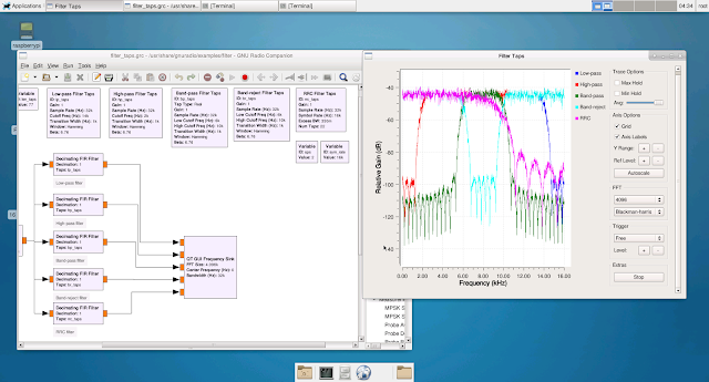
GNURadio Companion Qt Gui Frequency Sync - multiple FIR filter taps
sample running on Raspberry Pi 3 custom Linux distribution

The Raspberry Pi 3 is powered by the ARM Cortex-A53 processor. This 1.2GHz 64-bit quad-core processor fully supports the ARMv8-A architecture. For this project, a custom Linux distribution was created for the Raspberry Pi 3.  

The custom Linux distribution includes support for GNURadio, several FPGA and ARM Powered SDR devices, D-STAR (hotspot, repeater, and dongle support), hsuart, libusb, hardware real-time clock support, Sony 14 megapixel NoIR image sensor, HDMI and 3.5mm audio, USB Microphone input, X-windows with Xfce, Lighttpd and PHP, Bluetooth, WiFi, SSH, TCPDump, Docker, Docker registry, MySQL, Perl, Python, QT, GTK, IPTables, x11vnc, SELinux, and full native-toolchain development support.

The Sony 14 megapixel image sensor with the infrared filter removed can be connected to the Raspberry Pi 3's MIPI camera serial interface. Image capture and recognition can then be performed over contiguous periods of time, and time-lapsed video can be created from the images. With support for Tensorflow and OpenCV, object recognition within images can be performed.

D-STAR hotspot with time-lapsed infrared imaging.


For the initial run, an infrared Time-lapse Video was created from an initial image capture run of one 3280x2460 infrared jpeg image captured every 15 seconds for three hours. 40, 5mm, 940nm LEDs, powered by 500ma over 12v DC, provided infrared illumination in the 940nm wavelength.

Tensorflow ran in the background (on v4l2 kmod) and provided continuous object recognition and scoring within each image via a sample model. Finally, OpenCV was also installed in the root file system.

The time-lapse infrared video was captured of the living room using the above setup. Below this image are images of Tensorflow running in a terminal in the background on the Raspberry Pi 3 and recognizing/scoring objects in the living room.

Tensorflow running on the Raspberry Pi 3 and continuously capturing frames from the image sensor and scoring objects


GNURadio Companion running on xfce on the Raspberry Pi 3

Tuesday, August 16, 2016

Profiling Multiprocess C programs with ARM DS-5 Streamline

The ARM DS-5 Streamline Performance Analyzer is a powerful tool for debugging, profiling, and analyzing multithreaded and multiprocess C programs.  Instructions can easily be traced between load and store operations.  Per process and per thread function call paths can be broken down by system utilization percentage.  Branch mispredictions and multi-level CPU caches can be analyzed. Furthermore, disk I/O usage, stack and heap usage, and a number of other useful metrics can quickly be referenced within the debugger. These are just a few of its capabilities.

In order to capture meaningful information from the DS-5 Streamline Performance Analyzer tool, a Linux, multiprocess, C program was modified to insert 1000 packets into a packet processing simulation buffer.  A code excerpt from the program is below.  The child processes were modified to sleep and then wake 1000 times in order to simulate process activity.  The program was analyzed using the DS-5 Streamline Performance Analyzer tool.  There are two screenshots below the code excerpt where the program is loaded into the DS-5 Streamline Performance Analyzer.

void *insertpackets(void *arg) {

struct pktbuf *pkbuf;
struct packet *pkt;
int idx;

if(arg != NULL) {

pkbuf = (struct pktbuf *)arg;

/* seed random number generator */
...

/* insert 1000 packets into the packet buffer */
for(idx = 0; idx < 1000; ++idx) {

pkt = (struct packet *)malloc(sizeof(struct packet));

if(pkt != NULL) {

/* set the packet processing simulation multiplier to 3 */
pkt->mlt=...()%3;

/* insert packet in the packet buffer */
if(pkt_queue(pkbuf,pkt) != 0) {

...
...
...
...
...
...

int fcnb(time_t secs, long nsecs) {

struct timespec rqtp;
struct timespec rmtp;
int ret;
int idx;

rqtp.tv_sec = secs;
rqtp.tv_nsec = nsecs;

for(idx = 0; idx < 1000; idx++) {

ret = nanosleep(&rqtp, &rmtp);

...
...
... 
 
ARM DS-5 Streamline - Profiling the process creation application

ARM DS-5 Streamline - Code View with C code in the top window
and ARM assembly instructions in the bottom window

https://github.com/brhinton/de0-nano-soc/blob/main/run.c

Thursday, June 30, 2016

VHDL Processes for Pulsing Multiple GPIO Pins at Different Frequencies on Altera FPGA

 
DE1-SoC GPIO Pins connected to 780nm Infrared Laser Diodes, 660nm Red Laser Diodes, and Oscilloscope

The following VHDL processes pulse the GPIO pins at different frequencies on the Altera DE1-SoC using multiple Phase-Locked Loops. Several diodes were connected to the GPIO banks and pulsed at a 50% duty cycle with 16mA across 3.3V. Each GPIO bank on the DE1-SoC has 36 pins. Pin 1 is pulsed at 20Hz from GPIO bank 0, and pins 0 and 1 are pulsed at 30Hz from GPIO bank 1. A direct mode PLL with locked output was configured using the Altera Quartus Prime MegaWizard. The PLL reference clock frequency is set to 50MHz, the output clock frequency is set to 50MHz, and the duty cycle is set to 50%. The pin mappings for GPIO banks 0 and 1 are documented on the DE1-SoC datasheet.

Pulsed Laser Diodes via GPIO pins on DE1-SoC FPGA

- -- ---------------------
- -- CLOCK A AND B PROCESSES --
- -- INPUT: direct mode pll with locked output
- -- and reference clock frequency set to 50MHz,
- -- output clock frequency set to 50MHz with 50% duty
- -- cycle and output frequency scaled by freq divider constant
- -- ----------------------------------------------------------- 
clk_a_process : process (lkd_pll_clk_a)
begin
if rising_edge(lkd_pll_clk_a) then
if (cycle_ctr_a < FREQ_A_DIVIDER) then
cycle_ctr_a <= cycle_ctr_a + 1;
else
cycle_ctr_a <= 0;
end if;
end if;
end process clk_a_process;

clk_b_process : process (lkd_pll_clk_b)
begin
if rising_edge(lkd_pll_clk_b) then
if (cycle_ctr_b < FREQ_B_DIVIDER) then
cycle_ctr_b <= cycle_ctr_b + 1;
else
cycle_ctr_b <= 0;
end if;
end if;
end process clk_b_process; 
- -- ---------------------
- -- GPIO A AND B PROCESSES --
- -- INPUT: direct mode pll with locked output
- -- ------------------------------------------------------- 
gpio_a_process : process (lkd_pll_clk_a)
begin
if rising_edge(lkd_pll_clk_a) then
if (cycle_ctr_a = 0) then
gpio_sig_0 <= NOT gpio_sig_0;
end if;
end if;
end process gpio_a_process;

gpio_b_process : process (lkd_pll_clk_b)
begin
if rising_edge(lkd_pll_clk_b) then
if (cycle_ctr_b = 0) then
gpio_sig_1 <= NOT gpio_sig_1;
end if;
end if;
end process gpio_b_process;
GPIO_0 <= gpio_sig_0;
GPIO_1 <= gpio_sig_1;

Thursday, June 2, 2016

FPGA Audio Processing with the Cyclone V Dual-Core ARM Cortex-A9

The DE1-SoC FPGA Development board from Terasic is powered by an integrated Altera Cyclone V FPGA and ARM MPCore Cortex-A9 processor. The FPGA and ARM core are connected by a high-speed interconnect fabric. Linux can be booted on the ARM core and the FPGA and ARM core can communicate.

The DE1-SoC board below has been programmed via Quartus Prime running on Fedora 23, 64-bit Linux. The FPGA bitstream was compiled from the Terasic Audio codec design reference. After the bitstream was loaded on to the FPGA over the USB blaster II interface, the NIOS II command shell was used to load the NIOS II software image onto the chip. A menu-driven, debug interface is running from a terminal on the host via the NIOS II shell with the target connected over the USB Blaster II interface.

A low-level hardware abstraction layer was programmed in C to configure the on-board audio codec chip. The NIOS II chip is stored in on-chip memory and a PLL driven, clock signal is fed into the audio chip. The Verilog code for the hardware design was generated from Qsys. The design supports configurable sample rates, mic in, and line in/out.

Additional components are connected to the DE1-SoC board in this photo. The Linear DC934A (LTC2607) DAC is connected to the DE1-SoC and an oscilloscope is connected to the ground and vref pins on the DAC.

The DC934A features an LTC2607 16-Bit Dual DAC with i2c interface and an LTC2422 2-Channel 20-Bit uPower No Latency Delta Sigma ADC.

3.5mm audio cables are connected to the mic in and line out ports, respectively. The DE1-SoC is connected to an external display over VGA so that a local console can be managed via a connected keyboard and mouse when Linux is booted from uSD.

With GPIO pins accessible via the GPIO 0 and 1 breakouts, external LEDs can be pulsed directly from the Hard Processor System (HPS), FPGA, or the FPGA via the HPS.