Friday, September 16, 2016

Implementing Software-defined radio and Infrared Time-lapse Imaging with Tensorflow on a custom Linux distribution for the Raspberry Pi 3

GNURadio Companion Qt Gui Frequency Sync - multiple FIR filter taps
sample running on Raspberry Pi 3 custom Linux distribution

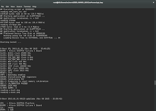
The Raspberry Pi 3 is powered by the ARM Cortex-A53 processor. This 1.2GHz 64-bit quad-core processor fully supports the ARMv8-A architecture. For this project, a custom Linux distribution was created for the Raspberry Pi 3.  

The custom Linux distribution includes support for GNURadio, several FPGA and ARM Powered SDR devices, D-STAR (hotspot, repeater, and dongle support), hsuart, libusb, hardware real-time clock support, Sony 14 megapixel NoIR image sensor, HDMI and 3.5mm audio, USB Microphone input, X-windows with Xfce, Lighttpd and PHP, Bluetooth, WiFi, SSH, TCPDump, Docker, Docker registry, MySQL, Perl, Python, QT, GTK, IPTables, x11vnc, SELinux, and full native-toolchain development support.

The Sony 14 megapixel image sensor with the infrared filter removed can be connected to the Raspberry Pi 3's MIPI camera serial interface. Image capture and recognition can then be performed over contiguous periods of time, and time-lapsed video can be created from the images. With support for Tensorflow and OpenCV, object recognition within images can be performed.

D-STAR hotspot with time-lapsed infrared imaging.


For the initial run, an infrared Time-lapse Video was created from an initial image capture run of one 3280x2460 infrared jpeg image captured every 15 seconds for three hours. 40, 5mm, 940nm LEDs, powered by 500ma over 12v DC, provided infrared illumination in the 940nm wavelength.

Tensorflow ran in the background (on v4l2 kmod) and provided continuous object recognition and scoring within each image via a sample model. Finally, OpenCV was also installed in the root file system.

The time-lapse infrared video was captured of the living room using the above setup. Below this image are images of Tensorflow running in a terminal in the background on the Raspberry Pi 3 and recognizing/scoring objects in the living room.

Tensorflow running on the Raspberry Pi 3 and continuously capturing frames from the image sensor and scoring objects


GNURadio Companion running on xfce on the Raspberry Pi 3

Tuesday, August 16, 2016

Profiling Multiprocess C programs with ARM DS-5 Streamline

The ARM DS-5 Streamline Performance Analyzer is a powerful tool for debugging, profiling, and analyzing multithreaded and multiprocess C programs.  Instructions can easily be traced between load and store operations.  Per process and per thread function call paths can be broken down by system utilization percentage.  Branch mispredictions and multi-level CPU caches can be analyzed. Furthermore, disk I/O usage, stack and heap usage, and a number of other useful metrics can quickly be referenced within the debugger. These are just a few of its capabilities.

In order to capture meaningful information from the DS-5 Streamline Performance Analyzer tool, a Linux, multiprocess, C program was modified to insert 1000 packets into a packet processing simulation buffer.  A code excerpt from the program is below.  The child processes were modified to sleep and then wake 1000 times in order to simulate process activity.  The program was analyzed using the DS-5 Streamline Performance Analyzer tool.  There are two screenshots below the code excerpt where the program is loaded into the DS-5 Streamline Performance Analyzer.

void *insertpackets(void *arg) {

struct pktbuf *pkbuf;
struct packet *pkt;
int idx;

if(arg != NULL) {

pkbuf = (struct pktbuf *)arg;

/* seed random number generator */
...

/* insert 1000 packets into the packet buffer */
for(idx = 0; idx < 1000; ++idx) {

pkt = (struct packet *)malloc(sizeof(struct packet));

if(pkt != NULL) {

/* set the packet processing simulation multiplier to 3 */
pkt->mlt=...()%3;

/* insert packet in the packet buffer */
if(pkt_queue(pkbuf,pkt) != 0) {

...
...
...
...
...
...

int fcnb(time_t secs, long nsecs) {

struct timespec rqtp;
struct timespec rmtp;
int ret;
int idx;

rqtp.tv_sec = secs;
rqtp.tv_nsec = nsecs;

for(idx = 0; idx < 1000; idx++) {

ret = nanosleep(&rqtp, &rmtp);

...
...
... 
 
ARM DS-5 Streamline - Profiling the process creation application

ARM DS-5 Streamline - Code View with C code in the top window
and ARM assembly instructions in the bottom window

https://github.com/brhinton/de0-nano-soc/blob/main/run.c

Thursday, June 30, 2016

VHDL Processes for Pulsing Multiple GPIO Pins at Different Frequencies on Altera FPGA

 
DE1-SoC GPIO Pins connected to 780nm Infrared Laser Diodes, 660nm Red Laser Diodes, and Oscilloscope

The following VHDL processes pulse the GPIO pins at different frequencies on the Altera DE1-SoC using multiple Phase-Locked Loops. Several diodes were connected to the GPIO banks and pulsed at a 50% duty cycle with 16mA across 3.3V. Each GPIO bank on the DE1-SoC has 36 pins. Pin 1 is pulsed at 20Hz from GPIO bank 0, and pins 0 and 1 are pulsed at 30Hz from GPIO bank 1. A direct mode PLL with locked output was configured using the Altera Quartus Prime MegaWizard. The PLL reference clock frequency is set to 50MHz, the output clock frequency is set to 50MHz, and the duty cycle is set to 50%. The pin mappings for GPIO banks 0 and 1 are documented on the DE1-SoC datasheet.

Pulsed Laser Diodes via GPIO pins on DE1-SoC FPGA

- -- ---------------------
- -- CLOCK A AND B PROCESSES --
- -- INPUT: direct mode pll with locked output
- -- and reference clock frequency set to 50MHz,
- -- output clock frequency set to 50MHz with 50% duty
- -- cycle and output frequency scaled by freq divider constant
- -- ----------------------------------------------------------- 
clk_a_process : process (lkd_pll_clk_a)
begin
if rising_edge(lkd_pll_clk_a) then
if (cycle_ctr_a < FREQ_A_DIVIDER) then
cycle_ctr_a <= cycle_ctr_a + 1;
else
cycle_ctr_a <= 0;
end if;
end if;
end process clk_a_process;

clk_b_process : process (lkd_pll_clk_b)
begin
if rising_edge(lkd_pll_clk_b) then
if (cycle_ctr_b < FREQ_B_DIVIDER) then
cycle_ctr_b <= cycle_ctr_b + 1;
else
cycle_ctr_b <= 0;
end if;
end if;
end process clk_b_process; 
- -- ---------------------
- -- GPIO A AND B PROCESSES --
- -- INPUT: direct mode pll with locked output
- -- ------------------------------------------------------- 
gpio_a_process : process (lkd_pll_clk_a)
begin
if rising_edge(lkd_pll_clk_a) then
if (cycle_ctr_a = 0) then
gpio_sig_0 <= NOT gpio_sig_0;
end if;
end if;
end process gpio_a_process;

gpio_b_process : process (lkd_pll_clk_b)
begin
if rising_edge(lkd_pll_clk_b) then
if (cycle_ctr_b = 0) then
gpio_sig_1 <= NOT gpio_sig_1;
end if;
end if;
end process gpio_b_process;
GPIO_0 <= gpio_sig_0;
GPIO_1 <= gpio_sig_1;

Thursday, June 2, 2016

FPGA Audio Processing with the Cyclone V Dual-Core ARM Cortex-A9

The DE1-SoC FPGA Development board from Terasic is powered by an integrated Altera Cyclone V FPGA and ARM MPCore Cortex-A9 processor. The FPGA and ARM core are connected by a high-speed interconnect fabric. Linux can be booted on the ARM core and the FPGA and ARM core can communicate.

The DE1-SoC board below has been programmed via Quartus Prime running on Fedora 23, 64-bit Linux. The FPGA bitstream was compiled from the Terasic Audio codec design reference. After the bitstream was loaded on to the FPGA over the USB blaster II interface, the NIOS II command shell was used to load the NIOS II software image onto the chip. A menu-driven, debug interface is running from a terminal on the host via the NIOS II shell with the target connected over the USB Blaster II interface.

A low-level hardware abstraction layer was programmed in C to configure the on-board audio codec chip. The NIOS II chip is stored in on-chip memory and a PLL driven, clock signal is fed into the audio chip. The Verilog code for the hardware design was generated from Qsys. The design supports configurable sample rates, mic in, and line in/out.

Additional components are connected to the DE1-SoC board in this photo. The Linear DC934A (LTC2607) DAC is connected to the DE1-SoC and an oscilloscope is connected to the ground and vref pins on the DAC.

The DC934A features an LTC2607 16-Bit Dual DAC with i2c interface and an LTC2422 2-Channel 20-Bit uPower No Latency Delta Sigma ADC.

3.5mm audio cables are connected to the mic in and line out ports, respectively. The DE1-SoC is connected to an external display over VGA so that a local console can be managed via a connected keyboard and mouse when Linux is booted from uSD.

With GPIO pins accessible via the GPIO 0 and 1 breakouts, external LEDs can be pulsed directly from the Hard Processor System (HPS), FPGA, or the FPGA via the HPS.

Sunday, November 8, 2015

Configuring the Altera Cyclone V FPGA SoC Boot loader on a DE0-Nano-SoC board

Understanding the boot loader on a computer system is probably the most important aspect of security. Most computer systems have multiple boot loaders that run in sequence immediately after a power reset is applied to the processor on the computer system.  This applies to embedded, desktop, and server systems.

The Altera Cyclone V SoC has an FPGA and a Hard Processor System (HPS) woven into a single processor package.  The HPS is a dual core ARM Cortex A9.  Building everything from scratch is the best way to figure out how the system works.

The boot sequence on a Cyclone V HPS works like this:

The On-chip ROM (for which source code is not provided) loads the preloader (1st stage bootloader). The preloader then loads U-boot. U-boot then loads the kernel and root file system.

There are two well thought out options for the preloader according to the Cyclone V boot guide.  The two options are licensed differently depending on how the source code is built. One is licensed under a BSD license and the other under GPL v2 with U-Boot.

Building a pre-loader image for the DE0-Nano-SoC board was straightforward.  Altera provides the bsp-editor utility for customizing the preloader configuration and generating the BSP HPS preloader source code, after which, make is used to build the sources using the Mentor ARM cross toolchain.
The preloader settings directory can be found on the DE0-Nano-SoC CD in the DE0_NANO_SOC_GHRD subdirectory.


The preloader load address can be set via the bsp-editor so that the on chip ROM either loads the preloader from an absolute zero address on the sdcard or from a fat partition with id equal to a2 on the sdcard.  These are the options for booting from the sdcard.


After the sources are generated and the preloader image is built using the Makefile, U-boot must be compiled. An Altera port of U-Boot is available on github for the Cyclone V FPGA SoC. U-Boot is built using the Linaro ARM cross toolchain.

There's quite a bit that can be done with the Cyclone V FPGA SoC boot configuration.  FPGA images can be loaded from U-boot.  The jumpers on the board can be configured to boot from the on-board serial flash (QSPI), bare metal applications can be loaded from the preloader, the FPGA can be configured from serial flash, and the list goes on.  The HPS SoC Boot Guide for the Cyclone V SoC  is a valuable reference and contains all of the boot configuration information.

Wednesday, October 28, 2015

The "Three Fives" Discrete 555 Timer Kit

The NE555 timer IC is a classic and widely used component in electronic circuits, so building a transistor-scale replica of it is a great way to understand how it works at a fundamental level. It's also a good way to develop your soldering skills and learn how to use an oscilloscope to measure signals in a circuit.

I picked up a "Three Fives" Discrete Timer Kit this weekend. As it turns out the kit was well worth the money. The "Three Fives" Discrete Timer Kit is a transistor-scale replica of the NE555 timer IC. The printed circuit board (PCB) is high-quality and soldering the transistors and resistors was alot of fun. Thanks to Eric Schlaepfer and Evil Mad Scientist Labs for this high quality circuit kit.

The size of the board makes it easy to measure what's going on inside the circuit. Just connect the probes from an oscilloscope to any of the solder or test points on the board.

A photo of the board that I built is below. I also wired a sample test circuit for blinking a pink LED and then connected a scope to the board so that I could look at the square wave.


Thursday, July 16, 2015

Creating a custom Linux BSP for an ARM Cortex-A9 SBC with Yocto 1.8 - Part III

In part III of this guide, the installation of the final image to the SD card will be covered.  The SD card will then be booted on the target.  Finally, audio recording and playback will be tested.

Part III of this guide consists of the following sections.

  1. Write the GNU/Linux BSP image to an SD card.
  2. Set the physical switches on the RioTboard (Internet of Things) to boot from the uSD or SD card.
  3. Connect the target to the necessary peripherals for boot.
  4. Test audio recording, audio playback, and Internet connectivity.

1.  Write the GNU/Linux BSP image to an SD card

At this point, the build should be complete, without errors.  The output should be as follows.


 real 254m28.335s
user 737m9.307s
sys 133m39.529s

Insert an SD card into an SD card reader, connect it to the host, and execute the following commands on the host.


 host]$ cd $HOME/src/fsl-community-bsp/build /tmp/deploy/images/imx6dl-riotboard
host]$ sudo umount /dev/sd<X>
host]$ sudo dd if=bsec-image-imx6dl-riotboard.sdcard of=/dev/sd<X> bs=1M
host]$ sudo sync


2. Set the physical switches on the RioTboard to boot from the uSD or SD card.


For booting from the SD card on the bottom of the target, set the physical switches as follows.
SD (J6, bottom) 1 0 1 0 0 1 0 1

For booting from the uSD card on the top of the target, set the physical switches as follows.
uSD (J7, top) 1 0 1 0 0 1 1 0

3. Connect the target to the necessary peripherals for boot.

There are two options

Option 1

Connect one end of an ethernet cable to the target. Connect the other end of the ethernet cable to a hub or DHCP server.  

Connect the board to the host computer via the J18 serial UART pins on the target.  This will require a serial to USB breakout cable.  Connect TX, RX, and GND to RX, TX, and GND on the cable. The cable must have an FTDI or similar level shifter chip. Connect the USB end of the cable to the host computer.

Connect the speakers to the light green 3.5 mm audio out jack and the microphone to the pink 3.5 mm MIC In jack.

Connect a 5V / 4 AMP DC power source to the target.

Run minicom on the host computer. Configure minicom at 115200 8N1 with no hardware flow control and no software flow control. If a USB to serial cable with an FTDI chip in it is used, then the cable should show up in /dev as ttyUSB0 in which case, set the serial device in minicom to /dev/ttyUSB0.

If this option was chosen, drop into U-boot after power on by pressing Enter on the host keyboard with minicom open and connected.

If enter is not pressed after power-on, the target will boot and a login prompt will appear.

A login prompt will not appear.

Option 2

Connect one end of an ethernet cable to the target. Connect the other end of the ethernet cable to a hub or DHCP server.  

Connect a USB keyboard, USB mouse, and monitor (via an HDMI cable) to the target.

Connect the speakers to the light green 3.5 mm audio out jack and the microphone to the pink 3.5 mm MIC In jack.

Connect a 5V / 4 AMP DC power source to the target.

A login prompt will now appear.

4. Test audio recording, audio playback, and Internet connectivity


Type root to log in to the target. The root password is not set.

Execute the following commands on the target

 root@imx6dl-riotboard: alsamixer 

Press F6.
Press arrow down so that 0 imx6-riotboard-sgtl5000 is highlighted.
Press Enter.
Increase Headphone level to 79<>79.
Increase PCM level to 75<>75.
Press Tab.
Increase Mic level to 59.
Increase Capture to 80<>80.
Press Esc.

 root@imx6dl-riotboard: cd /usr/share/alsa/sounds
root@imx6dl-riotboard: aplay *.wav

A sound should be played through the speakers.

 root@imx6dl-riotboard: cd /tmp
root@imx6dl-riotboard: arecord -d 10 micintest.wav

Talk into the microphone for ten seconds.

 root@imx6dl-riotboard: aplay micintest.wav

A recording should play through the speakers.

 root@imx6dl-riotboard: ping riotboard.org

An ICMP reply should be received.